Precision Ferroelectric Loop Tester Explained: Complete Guide to Radiant Technologies’ P–E Hysteresis Measurement System (2025 Edition)
What Is a Ferroelectric Loop Tester? — A Quick Primer
A ferroelectric loop tester is a specialized instrument designed to study how ferroelectric materials respond to electric fields. It works by applying carefully controlled electrical signals — such as AC, DC, or pulse waveforms — to a material sample and then measuring the resulting electrical responses like charge, current, and voltage.
From these measurements, the tester plots the polarization–electric field (P–E) hysteresis loop, which reveals how the material’s polarization changes as the electric field is cycled. This loop is the key signature of ferroelectric behaviour.
Modern ferroelectric testers are engineered for high precision and stability. They minimize electrical noise, synchronize timing with microsecond accuracy, and maintain a wide dynamic range. These features allow researchers and students to accurately determine important material properties such as the coercive field, remanent polarization, leakage current, imprint behavior, switching speed, and device endurance.
In simple terms, a ferroelectric loop tester helps visualize how a material stores and switches electric polarization — a fundamental step in designing ferroelectric capacitors, memory devices, and sensors.
Table of Contents
Why Radiant’s Precision Testers Are Widely Used?
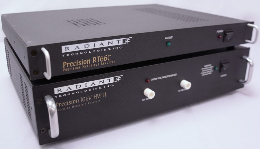
Radiant Technologies has been a pioneer in ferroelectric measurement systems, and its Precision series (including models like Premier II, Multiferroic II, LC II, and PiezoMEMS) is widely recognized in research laboratories and universities across the world. These instruments are valued not just for their performance but for how easily they adapt to different kinds of experiments — from thin films to bulk ceramics.
- Versatile Voltage Ranges
Radiant testers offer a broad range of voltage options, starting from ±10 V for delicate thin-film devices to ±500 V for thicker samples. For experiments that demand even higher fields, the voltage can be expanded up to 10 kV using external amplifier modules (HVA/HVI). This flexibility allows students and researchers to explore a wide spectrum of ferroelectric materials. - High-Resolution and Fast Data Capture
Each system is equipped with 18-bit analog-to-digital converters (ADCs) capable of capturing signals at multi-megahertz speeds. With the ability to record up to 32,000 data points per loop, users can visualize fine switching details and transient behaviors that would otherwise be missed in lower-resolution systems. - Broad Frequency and Timing Capability
Radiant instruments can perform both slow hysteresis loops for steady-state studies and high-speed tests reaching tens to hundreds of kilohertz. They are also capable of handling sub-microsecond pulse measurements, enabling detailed analysis of fast polarization dynamics and switching kinetics.
Together, these features make Radiant’s Precision systems ideal for studying both low-charge thin-film samples and high-voltage bulk ceramics. Their combination of precision, speed, and flexibility continues to make them a trusted choice in ferroelectric research and advanced material characterization.
Typical Signal Flow in a Ferroelectric Test System

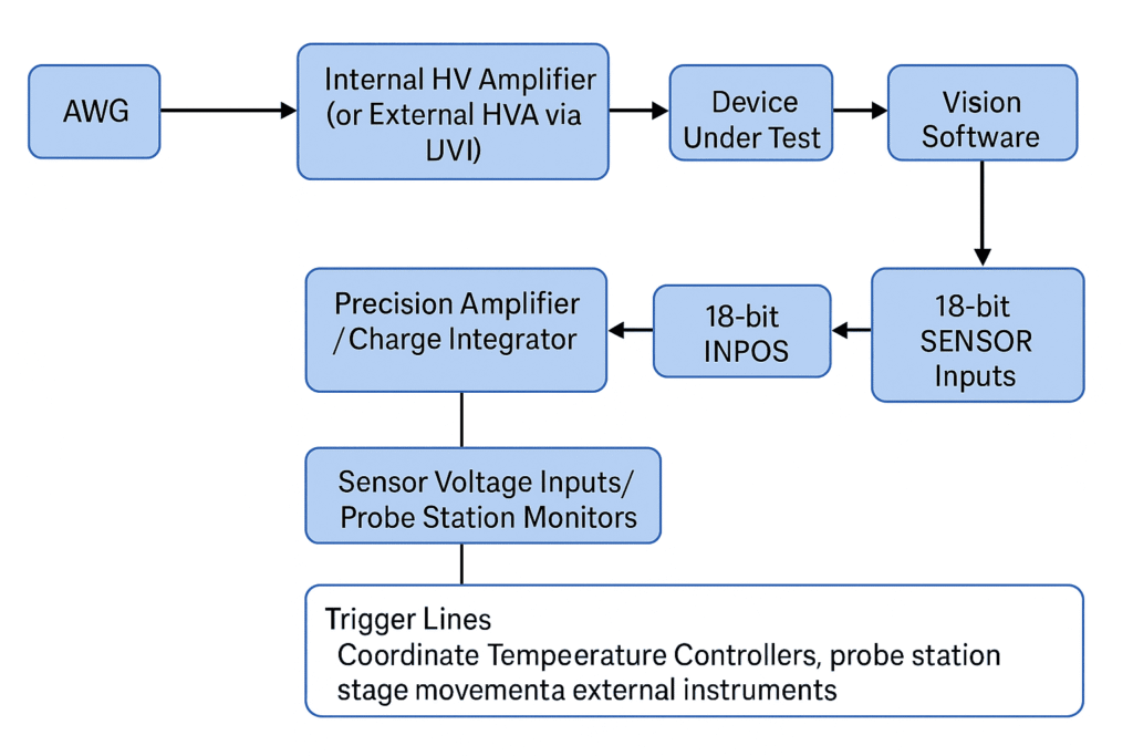
A ferroelectric tester operates as a precisely timed system where voltage generation, amplification, signal measurement, and data analysis all happen in perfect synchronization. The figure below shows how these components connect and work together inside the Radiant Precision system.
- Waveform Generation:
The process begins with the Arbitrary Waveform Generator (AWG), which creates voltage waveforms such as sine, triangle, or pulse shapes. - Voltage Amplification and Application to the Sample:
The AWG signal passes to an internal high-voltage amplifier, or to an external amplifier (HVA) through the high-voltage interface (HVI) when larger electric fields are required. The amplified voltage is then applied to the Device Under Test (DUT) — usually a ferroelectric capacitor, thin film, or ceramic pellet. - Charge and Current Measurement:
As the sample responds, the resulting charge or current flows into a precision charge amplifier or integrator, which converts these small signals into measurable electrical quantities. - Analog-to-Digital Conversion:
The amplified signals are digitized using a high-resolution 18-bit ADC, ensuring accurate capture of polarization switching events over time. - Data Processing and Visualization:
The digital data are then processed and displayed through Vision software, where users can analyze hysteresis loops, switching behavior, and material properties. - Sensor Inputs and Monitoring:
Optional sensor voltage inputs or probe station monitors can be connected to record auxiliary signals, such as temperature or external field variations. - Trigger and Synchronization Lines:
The tester’s trigger lines coordinate external devices like temperature controllers, probe station stages, or environmental chambers, ensuring all measurements occur under synchronized conditions.
Core Instrument Modules (Radiant Precision Chassis)
The Radiant Precision ferroelectric test systems are built on a versatile modular platform that brings together advanced hardware and software tools to study switching behavior in ferroelectric materials. Each module works in harmony to ensure accurate polarization–electric field (P–E) characterization and related measurements.
- Arbitrary Waveform Generator (AWG)
The system features a 16-bit Arbitrary Waveform Generator that can create various voltage waveforms such as sine, triangular, square, pulse, or custom shapes. This flexibility allows researchers to perform standard P–E loop tests, frequency sweeps, or tailor-made switching experiments with ease. - High-Voltage Amplifiers (Built-In and External Options)
Depending on experimental needs, the internal amplifiers can provide voltage ranges from ±10 V up to ±500 V. For higher field applications, external high-voltage modules extend the range up to 10 kV. This capability is especially useful when testing bulk ceramics or thick-film samples requiring strong electric fields. - Precision Charge and Current Measurement Unit
To capture even the smallest polarization changes, the system employs ultra-low-noise charge and current amplifiers. These front-end circuits can resolve charge levels down to the femtocoulomb range, making them ideal for thin-film or nanoscale devices where signals are extremely small. - High-Resolution Data Acquisition (ADCs)
The measurement accuracy is enhanced by 18-bit Analog-to-Digital Converters (ADCs) operating at multi-megahertz sampling rates. Each hysteresis loop can be recorded with tens of thousands of data points, providing excellent temporal resolution to study rapid switching events. - Precision Timing and Clock Synchronization
The timing system ensures perfect synchronization between waveform generation and signal acquisition. With a precision clock operating around 40 MHz, sub-microsecond pulse control becomes possible—an essential requirement for dynamic ferroelectric switching experiments. - Sensor and Differential Input Channels
Additional 18-bit sensor inputs are available for connecting external sensors, guard probes, or auxiliary voltage channels. These inputs make it possible to record multiple signals simultaneously or integrate the system with probe stations and charge amplifiers. - Digital I/O and Trigger Interfaces
Built-in digital I/O ports allow coordination with external devices such as probe stations, temperature controllers, or vacuum chambers. This feature supports automated test workflows and synchronized data collection during environmental or electrical cycling tests.
Accessories and External Hardware Commonly Used
A complete ferroelectric characterization setup often includes several auxiliary components that enhance measurement precision and versatility.
- High-Voltage Amplifier and Interface Modules
For experiments demanding electric fields beyond ±500 V, external high-voltage amplifier (HVA) and interface (HVI) modules extend the operating range up to 10 kV, enabling detailed studies on bulk ceramics and multilayer structures. - Probe Stations and Vacuum Chucks
Thin-film capacitors or microdevices are usually tested on probe stations equipped with vacuum chucks, micro-positioners, and fine tungsten tips. These setups allow precise electrical contact while minimizing noise and leakage. - Guarded Cabling and Triaxial Connectors
High-sensitivity charge measurements require well-shielded cabling. Triaxial connectors and guarded sample holders help suppress environmental noise and leakage currents, improving the reliability of small-signal measurements. - Temperature and Environmental Control Units
Temperature-dependent P–E loop or fatigue tests are performed using hot plates, cryostats, or vacuum chambers connected to the tester via trigger lines. These setups allow systematic studies of ferroelectric behavior under varied environmental conditions. - Optical Microscopy Tools
Stereo zoom microscopes with LED illumination are often used for device alignment and surface inspection before electrical probing. These tools help prevent damage to delicate electrodes and ensure accurate contact placement. - Shielded Enclosures and Faraday Cages
To reduce electromagnetic interference (EMI), sensitive experiments are typically performed inside shielded boxes or Faraday cages. This ensures that the measured signals represent the material’s intrinsic behavior, not electrical noise from the surroundings. - Computer and Data Acquisition System
The test system connects to a control PC through USB, GPIB, or Ethernet interfaces. The computer runs Vision Software, which manages waveform generation, data capture, and automated testing.
💻 Software Environment — Vision by Radiant Technologies
Vision is the dedicated software suite that powers Radiant’s Precision testers. It provides an intuitive interface for experiment setup, automation, and data analysis. Users can easily design test sequences for hysteresis (P–E) loops, PUND measurements, fatigue or retention studies, and even small-signal capacitance or DLTS tasks.
Vision also enables batch testing, recipe saving, and seamless data export for advanced analysis — making it a complete environment for both educational and research applications in ferroelectric materials science.
Measurement modes & what instrumentation elements they rely on?
Ferroelectric testers can perform a variety of measurement modes, each designed to reveal a specific property of the material. Every mode relies on certain key components within the test system to ensure accurate and repeatable results.
- P–E Hysteresis Measurement
This is the most fundamental test for ferroelectric materials. It measures how polarization (P) changes with the applied electric field (E). The test uses the Arbitrary Waveform Generator (AWG), high-voltage amplifier, precision charge measurement circuit, and a high-speed ADC.
Together, these components generate the voltage waveform, apply it to the sample, and record the resulting charge response with many data points per cycle. To ensure accuracy, the setup must have good electrical shielding and high sampling density to reduce noise and distortion. - PUND (Positive-Up Negative-Down) Measurement
The PUND test helps separate the switched charge (due to ferroelectric polarization) from the non-switched charge (due to leakage or capacitive effects). It uses a precisely timed pulse generator capable of delivering very fast pulses — often shorter than one microsecond — to the sample. Accurate timing and baseline correction are essential for reliable results. - Leakage Current or J–E Measurement
Leakage current tests examine how much current flows through a ferroelectric material under a constant or slowly varying DC voltage. These measurements depend on a stable high-voltage source and a sensitive current detection circuit, allowing researchers to distinguish between true polarization current and unwanted leakage paths. - Fatigue and Endurance Testing
To study how a material performs under repeated electrical cycling, the system performs long-duration automated pulse sequences. These experiments rely on robust automation, precise triggering, and effective thermal control to maintain stability over thousands or even millions of cycles. Vision software scripts and trigger I/O coordination make these tests smooth and consistent. - Small-Signal Capacitance and Impedance Measurements
Small-signal tests investigate how the capacitance of a ferroelectric material changes with frequency or bias. They use a tiny AC excitation voltage superimposed on a DC bias and measure the response using lock-in or impedance-based detection. The tester’s design must support both low- and high-frequency measurements to accurately capture dielectric and piezoelectric behaviors.
Example Technical Specifications — Radiant Precision Premier II & Multiferroic II
The Radiant Precision Premier II and Multiferroic II systems are among the most widely used ferroelectric testers in research laboratories. They combine high voltage drive capability, precise charge measurement, and fast data acquisition in one integrated platform. The following specifications represent typical values observed in these systems. (Exact features may vary depending on the model and firmware version.)
- Wide Voltage Range
These systems support multiple internal voltage options, including ±10 V, ±30 V, ±100 V, ±200 V, and ±500 V. For experiments that require stronger electric fields—such as testing bulk ceramics—the voltage range can be expanded up to 10 kV using an external High Voltage Amplifier (HVA) and Interface (HVI). - High-Resolution Data Conversion
Each system is equipped with 18-bit Analog-to-Digital Converters (ADCs), which enable precise measurement of small polarization signals and ensure accurate loop reconstruction even for thin-film capacitors. - Fast Data Capture
The testers operate with a 2 MHz capture rate per ADC, allowing detailed sampling of dynamic switching events. With interleaving, the system can achieve an even higher effective sampling rate, capturing up to 32,000 data points per hysteresis loop for fine time resolution. - High-Frequency Hysteresis Testing
Radiant systems are capable of performing high-speed hysteresis measurements. The Premier II typically operates at frequencies up to 250 kHz at ±10 V, while the Multiferroic II can reach around 270 kHz at ±100 V, depending on the specific configuration and load conditions. - Short Pulse Capability
These testers can generate and measure electrical pulses with widths shorter than one microsecond, enabling sub-µs pulse testing (down to approximately 500 ns in some setups). This feature is especially useful for studying rapid polarization switching kinetics. - High Data Density per Loop
Each P–E loop can include up to 32,000 individual data points, providing exceptional detail and allowing accurate visualization of fast switching behaviour across multiple cycles.
Best Practices for High-Precision Ferroelectric Measurements
Obtaining accurate and reproducible data in ferroelectric testing requires careful attention to experimental setup and measurement techniques. Following a few key best practices can greatly improve signal quality and ensure reliable results.
- Use Guarded and Triaxial Cabling
Always connect the measurement path using triaxial cables for charge-sensitive signals. The guard or driven shield in these cables minimizes current leakage and protects the signal from external noise. This setup is especially important when measuring very small charges from thin-film samples. - Keep Connections Short and Compact
Reducing the loop area and stray capacitance in your wiring helps prevent unwanted electrical pickup and improves system bandwidth. Using short, well-shielded leads between the sample and the tester enhances accuracy, especially during high-frequency or fast-pulse measurements. - Ensure Proper Temperature Stabilization
Temperature changes can strongly affect ferroelectric behavior. Before running precise P–E loop or retention measurements, allow the system to reach thermal equilibrium. Integrating temperature controllers within your test sequence ensures that every measurement is taken under stable conditions. - Run Baseline and Calibration Checks
Performing baseline, open, and short calibrations helps identify and correct for any leakage or offset in the measurement system. These quick checks make sure that the data you record represent the true behavior of your sample, not background system errors. - Select the Appropriate Voltage Range
Always choose a voltage range that matches your sample’s characteristics. Avoid driving the amplifier into saturation. For high-field testing, use an external High Voltage Amplifier (HVA) and adjust the gain to utilize the full dynamic range of the ADC without overloading it. - Balance Sampling Density and Bandwidth
Increasing the number of points per P–E loop gives smoother and more detailed curves, but it also requires higher sampling speed. Choose your sampling settings based on how quickly your material switches — slower materials need fewer points, while fast-switching samples benefit from higher capture rates.
Typical Laboratory Setup for a Radiant Ferroelectric Tester
Setting up a ferroelectric testing system in the lab requires a combination of precise instruments, proper wiring, and a stable environment. Each part of the setup plays a vital role in ensuring accurate, noise-free, and reproducible measurements. The following checklist can guide anyone—especially new researchers or students—who is preparing to install and operate a Radiant Precision tester.
- Radiant Precision Tester and Vision Software
The heart of the setup is the Radiant Precision tester, available in different models and voltage configurations (such as ±10 V to ±500 V, expandable up to 10 kV). It comes with Vision software, which provides complete control over waveform generation, data capture, and analysis. Together, they form the core system for all ferroelectric characterization tasks. - Probe Station or Sample Holder
To connect and measure samples effectively, a probe station or a vacuum chuck-based sample holder is essential. Probe stations with micropositioners and fine tungsten tips allow precise contact with small electrode areas on thin-film capacitors or microdevices. For bulk ceramics, a flat, vacuum-secured sample mount provides stable and repeatable connections. - Triaxial Cables and Guarded Connectors
Since ferroelectric measurements often deal with extremely small charge levels, signal integrity is crucial. Using triaxial cables, guarded connectors, and low-leakage fixtures ensures that signals are not corrupted by external interference or current leakage. Guarding also reduces noise and helps maintain accurate charge readings during fast or low-level measurements. - High-Voltage Amplifier and Interface (HVA/HVI)
For experiments requiring electric fields above ±500 V—such as bulk ceramic or high-field polarization studies—an external High-Voltage Amplifier (HVA) and High-Voltage Interface (HVI) are necessary. These modules safely extend the tester’s range up to 10 kV, allowing researchers to explore the full polarization behavior of high-field materials. - Temperature Controller or Environmental Chamber
Many ferroelectric properties are temperature-dependent. A temperature controller or environmental chamber allows the user to vary and monitor the test temperature precisely. By integrating this with the Vision software through trigger lines, measurements can be performed automatically at different temperatures to study thermal effects on polarization, coercive field, or fatigue behavior. - Faraday Cage or Shielded Enclosure
Electrical noise can significantly affect precision measurements. Placing the entire test setup inside a Faraday cage or shielded enclosure minimizes electromagnetic interference (EMI) and ensures that the data represent the true response of the material, not stray environmental signals. - Computer System with Vision Software and Data Backup
A dedicated PC with the Vision software installed is required for instrument control, waveform setup, and data acquisition. It’s good practice to maintain a reliable data backup system to preserve experimental results and analysis files.
How Radiant Compares to Other Ferroelectric Testers
In the world of ferroelectric research, Radiant Technologies’ Precision series has become a trusted name and a benchmark for accurate electrical characterization. These testers are widely used in universities, research institutes, and advanced materials labs because they combine a broad measurement range, high voltage capability, and user-friendly software.
The Precision family (including models like Premier II, Multiferroic II, and LC II) allows scientists to explore a wide variety of materials—from thin films to bulk ceramics—using a single, integrated platform. The system’s Vision software adds further flexibility by supporting automated experiments, batch testing, and detailed data visualization, making it popular for both teaching and research purposes.
Other companies also offer high-quality ferroelectric and piezoelectric testing solutions. For example, the aixACCT TF Analyzer systems are known for their modular design and strong performance in piezoelectric and MEMS characterization. They are especially well-suited for wafer-level or device-level studies that demand higher throughput and precise control over frequency and mechanical coupling.
In short, both Radiant and aixACCT systems serve important roles in modern laboratories—Radiant excels in academic research and general-purpose ferroelectric characterization, while aixACCT often finds its niche in industrial and piezoelectric device testing. The best choice depends on the voltage range, speed, and automation level your experiments require.
Purchasing and Service Guidance
When purchasing a ferroelectric tester, it’s essential to choose the right configuration for your research. Radiant Technologies and its authorized distributors provide customizable options for voltage ranges, high-voltage amplifiers, and probe station bundles.
Before ordering, always request the latest product brochure and an itemized quotation that includes all accessories. Many university core facilities list their existing Radiant systems—these listings can be valuable references for understanding common configurations and compatible modules.
Quick Troubleshooting Guide
Even the best instruments can occasionally show irregularities. Here are a few common issues you might encounter—and how to fix them effectively:
- Noisy Loops or Unstable Baseline
If your hysteresis loops look noisy or drift over time, inspect your shielding, grounding, and connector integrity. Running an open/short baseline calibration often helps stabilize the readings. - Distorted Loops at High Frequency
When loops appear compressed or distorted at higher test frequencies, check the amplifier’s slew rate and bandwidth. Make sure your drive voltage and series resistance are properly matched to the sample’s impedance. - Unexpectedly Low Polarization in Thin Films
Thin-film samples can produce smaller charge signals, so accurate area calibration and proper guarding are crucial. Also verify that your ADC dynamic range and sampling rate are set correctly to capture the full switching behavior.Radiant’s long-standing reputation, paired with its robust design and comprehensive software, makes it a reliable tool for anyone studying ferroelectric or piezoelectric materials. Whether you’re a student learning the basics or a researcher pushing the frontiers of materials science, understanding how these systems work—and how to maintain them—can help you get the best results from every experiment.
Thinking About Setting Up a Ferroelectric Test System?
If you’re planning to purchase or configure a Radiant Precision tester, it’s best to start with a clear understanding of your experimental needs. Before contacting the supplier, take a moment to outline a few important details — this will help you get the most accurate configuration and quotation.
Ask yourself:
- What is the maximum voltage your experiments will require?
- What is the sample size and the expected charge level during measurement?
- How fast do your materials switch — what is the highest frequency you’ll need to test?
- Will your experiments involve temperature variation or vacuum conditions?
Once you’ve defined these requirements, reach out to Radiant Technologies or their authorized distributors for a personalized quote or live demonstration. This ensures that your lab receives a system perfectly matched to its research goals — whether you’re studying thin films, ceramics, or advanced piezoelectric devices.
Taking this proactive approach not only helps in choosing the right configuration but also gives you confidence that your ferroelectric measurements will be accurate, efficient, and future-ready.
Why Investing in a Precision System Benefits Long-Term Research
Investing in a Radiant Precision ferroelectric tester is more than just adding another instrument to the lab — it’s about building a foundation for reliable, publishable, and repeatable research. These systems combine scientific accuracy with engineering flexibility, making them ideal for both academic exploration and industrial innovation.
For universities, owning a Radiant system opens up opportunities for hands-on learning, allowing students to directly observe how real materials exhibit polarization, switching, and fatigue behaviors. For research labs, it ensures long-term value through software upgrades, hardware expandability, and compatibility with evolving material studies — from thin films to next-generation MEMS and energy devices.
In short, a well-configured Precision system doesn’t just measure your materials — it empowers your research journey, helping you uncover new insights into the fascinating world of ferroelectric and piezoelectric materials.
Ferroelectric Loop Tester — Specs & Comparison Sheet
Compact one-page comparison of Radiant Precision Premier II, Radiant Precision Multiferroic II and aixACCT TF Analyzer (representative TF series). Vendor specs and published literature used as reference — confirm current datasheets for purchasing decisions.
| Feature / Parameter | Radiant Precision Premier II | Radiant Precision Multiferroic II | aixACCT TF Analyzer (TF 2000 E / TF series) |
|---|---|---|---|
| Typical Built-in Voltage Ranges | ±10 V, ±30 V, ±100 V, ±200 V, ±500 V | ±100 V, ±200 V, ±500 V (expandable) | TF 2000 E: modular voltage ranges (depends on selected module; can support kV-class with modules) |
| Expandable / External HV Capacity | Up to 10 kV with High Voltage Interface (HVI) + external amplifier (HVA) | Also expandable to 10 kV via external HV interface | Some TF modules support high-voltage modules; capability depends on model selection |
| Maximum Hysteresis / Loop Frequency | Up to ≈250 kHz (at ±10 V) — model/config dependent | ≈270 kHz (at ±100 V) — built-in spec for mid-voltage envelope | Depends on model; TF series supports dynamic loop measurement used in fast switching research |
| ADC / Digitizer Resolution & Capture Rate | 18-bit ADC; ~2 MHz single-pass capture; interleaving strategies for higher effective rates | Comparable 18-bit ADC and capture architecture; supports up to 32k points | Designed for ferroelectric/dielectric tests; published literature shows dense sampling — exact ADC specs vary by model |
| Maximum Data Points Per Loop | 32,000 points (max) | 32,000 points (same envelope) | Model/firmware dependent; many TF experiments use dense sampling |
| Minimum Pulse Width (Switching / PUND) | ~0.5 µs (sub-µs capability depending on config) | Comparable (depends on configuration) | TF series supports pulse tests; literature reports ~1 µs-class experiments |
| Maximum Pulse Width / Delay Between Pulses | Pulse widths up to ~1 s; long delays supported (order of 10⁴ s depending on sequence) | Similar generation/logic architecture — supports long pulse/delay windows | TF modules support wide dynamic range of pulse widths (µs to very long) depending on config |
| Minimum Measurable Charge / Sensitivity | ≈200 fC measurable in a 1-second pass (typical, lab conditions) | Similar sensitivity within the Precision family | TF analyzers used to resolve sub-nC switching; front-end design determines ultimate sensitivity |
| Small-Signal Capacitance / AC Test Frequency | Small-signal tests up to ~1 MHz (configuration dependent) | Similar small-signal support | TF analyzers support C–V / dielectric frequency sweeps in many module configurations |
| Environmental / Temperature Support | Integrates with thermal & environmental chambers via trigger / digital IO (ambient → elevated → cryo) | Same integration capability via Vision and hardware IO | TF systems commonly used with temperature/variable environment setups in research labs |
| Software / Automation | Radiant Vision software — ready tasks for hysteresis, PUND, fatigue, retention, etc. (robust automation) | Same Vision environment (common platform across Precision family) | aixACCT provides its own control and analysis software (modular architecture per model) |
| Typical Applications / Use Cases | Thin films, bulk ceramics, MEMS devices, reliability/fatigue/retention testing, research labs | Same spectrum; often used where mid-voltage/frequency envelope is needed | Electroceramics and thin films; dielectric/ferroelectric characterization in academic research |
| Strengths / Highlights | Broad voltage/frequency envelope, high precision front end, mature software, wide adoption in research | Slightly higher built-in frequency range for mid-voltage settings; same Precision family quality | Modular flexibility; strong for piezo/ferroelectric/dielectric domains; proven in academic studies |
| Considerations / Tradeoffs | For >500 V operation, external HV modules required; cost increases with optional modules | External HV needed for extreme fields; internal choices may influence max loop speed | May require careful module selection/customization to match exact voltage/frequency needs |
Precision Ferroelectric Loop Tester — FAQs 2025 Edition
Radiant Technologies’ P–E System • Vision Software • PUND • Best Practices
1) What is a Precision Ferroelectric Loop Tester?
2) What makes the Precision Premier II / Multiferroic systems unique?
3) What is the role of Vision Software?
4) What does a P–E hysteresis loop reveal?
5) How is leakage separated from true switching current (PUND)?
6) Which sample types are supported?
7) What does a typical P–E setup include?
8) How is accuracy ensured?
9) Static vs. dynamic hysteresis measurements—what is the difference?
10) Common errors and mitigation?
11) Can I run temperature-dependent P–E measurements?
12) How do I export and analyze data?
13) Why is PUND essential?
14) How do Radiant systems support relaxor research?
15) Is it suitable for industrial workflows?
16) What’s new in the 2025 edition?
17) How can I learn to operate the system effectively?
18) How does this system aid smart materials research?
References
Radiant Technologies — Precision Premier II Brochure. Available at: https://www.ferrodevices.com/download/4560/precision-premier-ii-brochure.pdf
Radiant Technologies — Multiferroic II Product Page. Available at: https://www.ferrodevices.com/precision-non-linear-materials-testers/
aixACCT Systems — TF Analyzer Family Overview. Available at: https://www.aixacct.com/en/testsysteme/tf-analyzer-family/
Seoul National University — TF 2000E Equipment Profile (aixACCT). Available at: https://recfi.snu.ac.kr/users/rcfi/equipment/TF2000E_aixACCT.pdf
Li et al., Chemistry of Materials, 27 (2015). DOI: https://doi.org/10.1021/acs.chemmater.5c00181
Yang et al., Journal of Applied Physics, 128 (2020). DOI: https://doi.org/10.1063/5.0032945
Ramanathan et al., Ceramics International, 48 (2022). DOI: https://doi.org/10.1016/j.ceramint.2022.02.020

Dr. Rolly Verma
- This post is intended purely for educational and informational purposes to support learning and research in materials science and nanotechnology.
- At present, this website does not contain any affiliate links or paid promotions. However, in the future, some articles may include affiliate links to recommended books, tools, or resources. If you make a purchase through those links, it will be at no additional cost to you, and it will help sustain this website’s free educational content.
- All brand and product names mentioned are the property of their respective owners. For complete information, please refer to our Disclosure, Disclaimer & Feedback Policy page once it is published
📘 Related Reading — Continue Exploring Ferroelectric Research
If you found this guide on Radiant’s Precision Ferroelectric Loop Tester helpful, explore these related articles to deepen your understanding of ferroelectric measurements and material behavior:
-
Ferroelectric Hysteresis Loop Artifacts: Causes, Identification & Correction
Understand common experimental artifacts in P–E hysteresis loops, their causes, and practical strategies to eliminate them for more accurate data. -
Non-Remnant Polarization: Key Points Every Researcher Should Know
Learn how non-remnant polarization differs from true ferroelectric switching and why recognizing it is crucial for accurate characterization. -
How to Perform a PUND Measurement: Step-by-Step Procedure
A detailed guide to the Positive-Up Negative-Down (PUND) method — including waveform setup, test conditions, and result interpretation.
If you notice any inaccuracies or have constructive suggestions to improve the content, I warmly welcome your feedback. It helps maintain the quality and clarity of this educational resource. You can reach me at: advancematerialslab27@gmail.com