
Why Does a Capacitor Block DC but Allow AC — and Why Is It Still Essential in DC Circuits?
The Complete Tutorial — Capacitive Reactance, Decoupling, Filtering, Ripple, Leakage Current and Capacitor Selection, Explained with Practical Examples
Introduction: The Common Belief
One of the most common beliefs among students is that capacitors only work in AC circuits and are useless in DC-powered systems. You have probably heard it — or even said it — during a viva exam: "Capacitors block DC and allow AC to pass."
While this statement is technically correct under ideal conditions, it is not the whole truth. If capacitors truly did not function in DC circuits, then how do our mobiles, laptops, and countless electronic gadgets — all powered by DC from batteries — rely so heavily on them? Open any smartphone teardown and you will find hundreds of capacitors on a board powered entirely by a DC battery. Clearly, something deeper is going on.
A capacitor conducts current only when the voltage across it changes (I = C dV/dt). Under steady DC (f = 0), its reactance X꜀ = 1/(2πfC) becomes infinite, so once fully charged it passes no current — it blocks DC. Under AC, the voltage changes continuously, so the capacitor keeps charging and discharging and current flows. Yet capacitors remain essential in DC circuits because real DC voltage is never perfectly constant: switching transistors, processors and regulators create ripple, noise and load transients every microsecond. Connected in parallel with the supply, capacitors act as local energy reservoirs — discharging when the voltage dips and recharging when it rises — keeping DC power stable, clean and reliable.
A capacitor operates on the principle of charging and discharging, allowing current to flow only when the voltage across it changes with time. In an AC circuit, the voltage continuously varies, so the capacitor keeps charging and discharging, enabling current to flow. In contrast, when connected to a DC source, the capacitor charges until its voltage equals the supply voltage. Once fully charged, the voltage no longer changes, the current becomes zero, and the capacitor behaves like an open circuit. That is why we say a capacitor blocks steady DC — yet, as this tutorial will show step by step, it remains indispensable for maintaining stable and reliable DC operation in every real electronic system.
This single relation is the key to the entire tutorial. Keep it in mind: no voltage change, no current. Fast voltage change, large current.
- What Textbooks Say: The Simplified DC Behaviour
- What Really Happens When DC Is Applied (RC Charging)
- The Second Lens: Capacitive Reactance (X꜀ = 1/2πfC)
- The Hidden Truth: No Capacitor Blocks DC Perfectly
- If Capacitors Block DC, How Do Mobiles and Laptops Still Work?
- How the Capacitor Acts as a Power Buffer (Water Tank Analogy)
- The Physics of DC Stabilization
- Decoupling in Practice: ESR, ESL and Capacitor Placement
- Filtering Rectified DC: The Ripple Voltage Formula
- Choosing the Right Capacitor for a DC Circuit
- Why Students Get Confused
- Major Roles of Capacitors in DC Circuits (Summary Table)
- Conceptual Summary
- Practice Questions (GATE-Style MCQs)
- Related Tutorials
- Frequently Asked Questions (FAQs)
- References
1. What Textbooks Say: The Simplified DC Behaviour
In basic circuit theory, when a DC voltage source is connected to a capacitor through a resistor, the capacitor charges up until its voltage equals the supply voltage. Once fully charged, current ceases to flow. This leads to the familiar interpretation:
"A capacitor allows AC to pass but blocks DC."
This is accurate only under steady-state conditions, where the DC supply remains constant and unchanging. But in real electronic systems, voltage rarely stays perfectly steady — and that single difference is where the entire story of this tutorial begins.
2. What Really Happens When DC Is Applied
Let us imagine a simple circuit where a DC battery is connected to a capacitor through a resistor.
At the instant of connection (t = 0), the capacitor initially behaves like a short circuit. Current flows rapidly as charge begins to accumulate on its plates. As time progresses, the voltage across the capacitor rises according to the classic exponential charging law:
During this process, the capacitor stores electrical energy given by:
Suppose a 100 µF capacitor is charged from a 5 V battery through a 1 kΩ resistor.
So within half a second, the current has fallen from 5 mA to essentially zero. From this moment onward, the capacitor "blocks DC". In fast digital circuits the resistances are far smaller, so this whole process happens in microseconds or less.
After the capacitor becomes fully charged, its voltage equals the battery voltage. There is no potential difference left to drive current, so the current drops to zero and the circuit behaves as an open circuit. This is why we say a capacitor blocks DC current — not because it rejects DC, but because after being charged, it simply has no reason to pass any more current. A clear conceptual treatment of this charging process is available in the HyperPhysics capacitor charging notes.
Notice that at t = 0, an uncharged capacitor briefly behaves like a short circuit. If the series resistance is very small — say only 0.1 Ω of wiring — a 5 V supply would try to push a momentary 50 A inrush current into the capacitor. This is why large capacitor banks in power supplies often need soft-start circuits or inrush-limiting resistors, and why fuses can blow at the instant a device is switched on.
3. The Second Lens: Capacitive Reactance (X꜀ = 1/2πfC)
So far we have explained the capacitor's behaviour through charging physics: I = C dV/dt. There is a second, equally powerful way to see the same truth — the one your examiner most likely expects in a viva or a GATE/JEE answer. It is called capacitive reactance.
Reactance (X꜀) is the opposition a capacitor offers to the flow of alternating current, measured in ohms just like resistance. Unlike resistance, however, reactance depends on frequency:
Now watch what happens at the two extremes:
- For DC: the frequency is zero (f = 0). Substituting, X꜀ = 1/0 → infinity. Infinite opposition means zero steady current — the capacitor blocks DC.
- For AC: the frequency is finite, so X꜀ has a finite value and current flows. And the higher the frequency, the smaller the reactance — a capacitor passes high-frequency signals more easily than low-frequency ones.
The same component behaves as an open circuit, a moderate impedance, or nearly a wire — depending only on frequency. This frequency-selective behaviour is the foundation of every filter, coupling and bypass application in this tutorial.
Both explanations — I = C dV/dt and X꜀ = 1/(2πfC) — describe the same physics from different angles. The first tells you why (current needs a changing voltage); the second tells you how much (quantifying the opposition at any frequency). A strong exam answer mentions both.
Here is a subtlety worth appreciating: even when AC "flows through" a capacitor, no electron ever crosses the dielectric. Electrons pile up on one plate and drain from the other, reversing every half cycle — the circuit current is real, but inside the gap it is carried by the changing electric field, which Maxwell named the displacement current. So "passing AC" really means the capacitor charges and discharges fast enough that, from outside, current appears continuous. This insight completed Maxwell's equations and predicted electromagnetic waves.
4. The Hidden Truth: No Capacitor Blocks DC Perfectly
Here is something most textbooks skip entirely: even the statement "a fully charged capacitor passes zero current" is an idealisation. In reality, every capacitor leaks.
The dielectric between the plates — the insulating material that makes a capacitor a capacitor — is never a perfect insulator. A tiny leakage current always flows through it, even under steady DC. You can model a real capacitor as an ideal capacitor with a very large resistor connected in parallel (called the insulation resistance).
- Aluminium electrolytic capacitors leak the most — typically microamps. A charged electrolytic left on a shelf loses its voltage within hours to days.
- Tantalum capacitors leak less, but still measurably.
- Ceramic and film capacitors leak the least — often nanoamps or below — and can hold charge for very long periods.
Why does this matter? In battery-powered devices, the leakage of every capacitor adds up to a small but permanent drain on the battery — one of the reasons a phone loses charge even when switched off. And in precision analogue circuits such as sample-and-hold stages or long RC timers, leakage sets a real limit on how long a capacitor can "remember" a voltage. Manufacturers such as TDK specify leakage current (or insulation resistance) on every capacitor datasheet for exactly this reason.
5. If Capacitors Block DC, How Do Battery-Powered Devices Like Mobiles and Laptops Still Work?
It may seem logical to assume that capacitors have no role in DC systems, since a battery provides constant voltage. However, in practical electronic systems — especially compact, high-speed devices such as smartphones and laptops powered entirely by DC — capacitors are indispensable for ensuring stable and noise-free operation. How?
This is because in real-world electronic circuits, the voltage from a battery is never perfectly constant. Every switching transistor, logic gate and microprocessor inside a device performs millions (or billions) of operations per second, creating tiny, rapid fluctuations in current demand. These fluctuations momentarily disturb the supply voltage, causing voltage dips and spikes known as transients.
At this stage, capacitors act as buffers between the battery and the circuits — absorbing these fluctuations and delivering smooth, reliable power.
A modern laptop processor can change its current demand by tens of amperes within nanoseconds when it switches between idle and full load. No battery or regulator can respond that fast through the resistance and inductance of the board — only capacitors placed millimetres from the chip can. This is why processor power-delivery networks use dozens to hundreds of capacitors of different sizes.
6. How the Capacitor Acts as a Power Buffer
To counter these voltage transients, capacitors are connected in parallel with the power supply rails. A capacitor in this configuration does not conduct DC continuously; instead, it responds dynamically to voltage variations, acting as a local energy reservoir.
In such a circuit, the current through the capacitor is governed by the same fundamental relation, I = C (dV/dt). This means current flows through the capacitor only when the voltage across it changes:
- When the load suddenly demands more current and the supply voltage begins to dip, the capacitor discharges momentarily, releasing stored energy to stabilize the voltage.
- When the load demand decreases and the voltage tends to rise, the capacitor absorbs excess charge, recharging itself and preventing overshoot.
The Water Tank Analogy
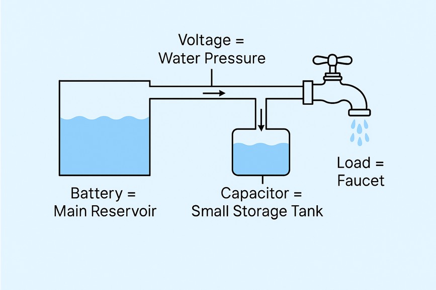
The diagram above illustrates the water tank analogy — a simple yet powerful way to understand how a capacitor stabilizes voltage in a DC circuit.
In this analogy, voltage is compared to water pressure, and electric current corresponds to the flow of water. The battery acts like a main reservoir, providing a steady flow of water through a pipe, which represents the conducting wires. The load — such as a smartphone circuit or an LED — is shown as a faucet that draws water (current) from the system.
- When the faucet opens suddenly, pressure drops — just as voltage dips when current demand increases. The small tank immediately releases water, maintaining pressure.
- When the faucet closes, the tank refills — like a capacitor recharging when voltage rises.
Thus, the capacitor continually stores and releases charge, keeping the voltage stable even during rapid fluctuations. In electronic devices this happens in microseconds, ensuring processors and circuits receive smooth, clean DC power. It is the reason capacitors are found near almost every IC, processor and power rail inside battery-powered systems like laptops and smartphones. SparkFun's beginner tutorial on capacitors is an excellent visual companion to this idea.
7. The Physics of DC Stabilization
Every battery, no matter how good, has internal resistance and inductance. So do the copper traces of the circuit board that carry current from the battery to each chip. When a circuit suddenly draws more current, the voltage at the load momentarily dips — the battery simply cannot deliver charge fast enough through this resistive–inductive path.
Capacitors placed near the IC pins — called decoupling capacitors (or bypass capacitors) — instantly discharge to fill the gap, keeping the voltage stable. Once the surge passes, they quietly recharge from the battery. This rapid charge–discharge cycle happens millions of times per second in modern high-speed digital circuits.
Moreover, power management ICs (PMICs) inside phones and laptops use switching regulators to convert the battery's voltage (around 3.7 V for a lithium-ion cell) into multiple regulated outputs (1.2 V, 1.8 V, 5 V, and so on). These switching converters inherently generate ripple, which capacitors must filter at both the input and output stages. Hence, capacitors are indispensable for filtering and stabilizing DC power in all modern electronic systems.
8. Decoupling in Practice: ESR, ESL and Capacitor Placement
Now that we understand why decoupling capacitors are needed, let us look at how engineers actually use them. This is where a beautiful piece of non-ideal physics enters the story.
Real Capacitors Have ESR and ESL
A real capacitor is not just a capacitance C. It also contains:
- ESR (Equivalent Series Resistance) — a small internal resistance from the electrodes, leads and dielectric losses. Every charge–discharge cycle pushes current through this resistance, causing voltage drops and heating. Low ESR means faster, cleaner energy delivery.
- ESL (Equivalent Series Inductance) — a tiny inductance from the leads and internal geometry, typically around a nanohenry for small surface-mount parts.
Self-Resonant Frequency: Why One Capacitor Is Never Enough
Because a real capacitor contains both C and ESL, it behaves like a series LC circuit. It works as a capacitor only below its self-resonant frequency (SRF); above the SRF, the inductance dominates and the "capacitor" actually behaves like an inductor!
This is why circuit boards use capacitors of several different values in parallel on the same rail: a bulk electrolytic (say 10–100 µF) handles slow, large fluctuations; a 100 nF ceramic handles mid-frequency noise; and even smaller ceramics (1–10 nF) placed closest to the chip handle the fastest transients. Each capacitor covers the frequency band where it still behaves capacitively. Texas Instruments' application note on bypass capacitor selection gives a thorough engineering treatment of this practice.
A decoupling capacitor must be placed as close as physically possible to the IC power pin, with the shortest, widest traces. Every millimetre of trace adds inductance, which delays the capacitor's response exactly when nanosecond speed is needed. This is why you see tiny capacitors clustered tightly around every processor on a motherboard.
9. Filtering Rectified DC: The Ripple Voltage Formula
So far we have discussed battery-powered systems. But most "DC" in the world actually starts life as AC from the wall socket, converted by a rectifier. And a rectifier alone does not produce smooth DC — it produces a bumpy, pulsating waveform.
A large smoothing (filter) capacitor placed after the rectifier stores charge during each voltage peak and releases it during each dip, filling in the valleys of the waveform. The small residual fluctuation that remains is called ripple voltage, and for a full-wave rectifier it is well approximated by:
A full-wave rectifier runs from 50 Hz mains (so ripple frequency f = 100 Hz) and supplies a load current of 1 A. With a 4700 µF filter capacitor:
Notice two lessons: larger capacitance means smaller ripple, but even a very large capacitor leaves some ripple behind. That is why practical power supplies follow the filter capacitor with a voltage regulator, which actively removes the remaining fluctuation.
This capacitor-input filter arrangement is the standard first stage of nearly every mains-powered DC supply, from phone chargers to laboratory bench supplies; the Encyclopaedia Britannica entry on capacitors gives a good general background on the device itself.
10. Choosing the Right Capacitor for a DC Circuit
Not all capacitors are equal, and choosing the wrong type is one of the most common practical mistakes in electronics. Each family of capacitors is defined by its dielectric material, and the dielectric determines everything: capacitance range, ESR, leakage, stability and cost.
| Capacitor Type | Typical Range | Strengths | Limitations | Typical DC-Circuit Role |
|---|---|---|---|---|
| Aluminium electrolytic | 1 µF – 100,000 µF | Very large capacitance per rupee; ideal for bulk storage | Polarised, high ESR, high leakage, limited lifetime, dries out with heat | Rectifier smoothing, bulk energy storage on supply rails |
| Ceramic (MLCC) | 1 pF – ~100 µF | Tiny, cheap, very low ESR/ESL, excellent at high frequency | Class 2 types lose capacitance with DC bias and temperature | Decoupling/bypass next to every IC pin |
| Tantalum / polymer | 0.1 µF – 1000 µF | Stable, compact, low ESR (polymer) | Polarised; tantalum can fail short if overstressed | Compact bulk decoupling in phones and laptops |
| Film (polyester, polypropylene) | 100 pF – 10 µF | Very low leakage, precise, self-healing, non-polarised | Physically larger, costlier per µF | Precision timing, snubbers, audio coupling |
| Supercapacitor | 0.1 F – thousands of F | Enormous capacitance; bridges the gap toward batteries | Low voltage per cell (~2.7 V), higher ESR, self-discharge | Memory backup, energy harvesting storage, burst power |
Rule 1 — Respect polarity. Electrolytic and tantalum capacitors are polarised: they have a marked positive and negative terminal and must be connected the right way round in a DC circuit. Reverse the polarity and the dielectric breaks down — electrolytics can overheat, vent, or burst, and tantalums can fail as a short circuit. Ceramic and film capacitors are non-polarised and can be connected either way.
Rule 2 — Charged capacitors can bite. A large filter capacitor can hold a dangerous charge for minutes or even hours after the device is unplugged — this is exactly the energy-storage ability we have praised throughout this tutorial. Camera flash circuits and mains power supplies are the classic hazards. Technicians always discharge large capacitors through a suitable resistor before touching a circuit. Never assume a switched-off device is a safe device.
Here is where electronics meets materials science directly. The high-capacitance Class 2 ceramic capacitors (X5R, X7R) that decouple every modern processor owe their performance to ferroelectric perovskite dielectrics — chiefly barium titanate (BaTiO₃) — whose spontaneous polarisation gives them enormous permittivity. Research on perovskite ferroelectrics, including lead-free systems such as Bi₀.₅Na₀.₅TiO₃-based ceramics [8], directly feeds into the next generation of capacitor dielectrics with better temperature stability and energy density. If you want to go deeper, see our tutorial Why Is Perovskite Piezoelectric?
11. Why Students Get Confused
The confusion arises because school-level DC circuit models are deliberately simplified. In those models:
- The voltage is perfectly constant,
- The capacitor charges exactly once,
- Then current stops — so it "blocks DC."
However, in real-world electronics, the DC voltage fluctuates continuously on microsecond timescales. Therefore, the statement "capacitors don't work in DC" is true only for ideal textbook circuits — never for dynamic real systems. The moment you remember that a capacitor responds to change, not to the average value of the voltage, the confusion disappears permanently.
If an examiner asks "Do capacitors work in DC circuits?", the complete answer is: "A capacitor blocks steady-state DC current when in series, but in parallel with a DC supply it is essential — it filters ripple, decouples noise, and acts as a local energy reservoir during load transients, because real DC voltage always fluctuates." That one sentence shows genuine understanding.
12. Major Roles of Capacitors in DC Circuits
Even though mobile devices and laptops are powered by DC batteries, their internal circuits are far from static. CPUs, GPUs, memory units and sensors constantly switch states, drawing highly variable current pulses. Without capacitors to stabilize the voltage, these transients would cause noise, instability or outright malfunction. The table below summarizes every major job capacitors perform in DC systems.
| Function | What It Does | Where You See It |
|---|---|---|
| Filtering / Smoothing | Removes ripple and noise from DC voltage after rectification or switching regulation. | Phone chargers, laptop and mobile power regulators. |
| Decoupling / Bypassing | Provides local energy storage to ICs, preventing voltage drops during sudden current demands. | Every microprocessor, GPU and IC power pin. |
| Energy Storage | Temporarily stores charge and releases it when load current spikes. | Camera flash circuits, supercapacitor backup systems. |
| Timing / Delay Circuits | Works with resistors to set RC time constants for control and oscillator circuits. | Power sequencing in laptops, 555-timer circuits, embedded systems. |
| Coupling (Signal Paths) | Passes AC signal components while blocking the DC offset between stages. | Audio amplifiers in mobile phones. |
| Soft-Start / Inrush Control | Shapes how quickly voltage rises at power-up, protecting components from current surges. | Power supply and motor-driver start-up circuits. |
| Snubbing / Transient Suppression | Absorbs voltage spikes generated when inductive loads or switches turn off. | Relay drivers, DC motor controllers, switching converters. |
13. Conceptual Summary
While a capacitor blocks steady DC current when connected in series, it becomes a vital component in DC-powered circuits when connected in parallel. Its main function is to serve as a local energy reservoir, instantly responding to rapid changes in load current and voltage. By supplying or absorbing charge as needed, it maintains stable voltage levels, reduces noise, and improves system reliability.
Along the way we also uncovered the deeper, real-world layers of the story:
- The "blocking" happens only after an exponential charging transient with time constant τ = RC.
- The reactance view says the same thing quantitatively: X꜀ = 1/(2πfC) is infinite at f = 0 (DC) and shrinks as frequency rises — and even in AC, current crosses the dielectric only as Maxwell's displacement current.
- Even a "fully charged" capacitor passes a small leakage current — no dielectric is perfect.
- Real capacitors carry ESR and ESL, which limit how fast they respond and set a self-resonant frequency — the reason boards use multiple capacitor values in parallel.
- Filter capacitors reduce rectifier ripple according to Vripple ≈ I/(fC), but a regulator is still needed for truly smooth DC.
- The choice of dielectric material — electrolytic, ceramic, film or ferroelectric perovskite — determines which job a capacitor can do.
14. Practice Questions (GATE-Style MCQs)
Test your understanding with these three questions. The correct answer is highlighted, with a short explanation below each question.
15. Related Tutorials on AdvanceMaterialsLab.com
If you enjoyed this tutorial, these related lessons build directly on the same physics of charge, polarisation and dielectrics:
Frequently Asked Questions (FAQs)
A capacitor conducts current only while the voltage across it is changing (I = C dV/dt). Under steady DC, once the capacitor is fully charged, dV/dt = 0, so the current becomes zero and it acts like an open circuit. Under AC, the voltage changes continuously, causing continuous charging and discharging — so current keeps flowing through the circuit.
When DC is initially applied, the capacitor draws a transient charging current. This current decreases exponentially (with time constant τ = RC) as the capacitor voltage approaches the supply voltage, until no more current flows and the capacitor behaves like an open circuit.
A rectifier produces pulsating, not smooth, DC. Filter capacitors smooth this output by storing charge during voltage peaks and releasing it during dips, reducing unwanted ripple and fluctuations. This produces a more stable DC voltage, improving performance and protecting downstream components.
In coupling, a series capacitor passes AC signals from one stage to another while blocking DC offsets. In decoupling, a parallel capacitor stabilizes the supply voltage by absorbing noise, spikes and transient fluctuations, preventing interference in sensitive circuit sections.
Higher capacitance provides better smoothing because more stored charge means smaller ripple amplitude (Vripple ≈ I/(fC)). However, excessively large capacitance causes high inrush current at power-up, larger physical size, higher cost and slower response — so practical designs balance these factors.
Different capacitors have different voltage ratings, ESR, ESL, dielectric types, leakage currents and tolerances. Choosing the wrong capacitor may lead to overheating, noise problems, poor filtering or circuit failure. Electrolytics suit bulk storage; low-ESL ceramics suit high-speed decoupling; film capacitors suit precision and low-leakage roles.
No. A capacitor can significantly reduce ripple but cannot eliminate it completely, because it must discharge slightly between charging peaks. For very smooth DC, additional stages such as LC/RC filter networks and, above all, voltage regulators are used after the smoothing capacitor.
Not perfectly. Every real dielectric passes a tiny leakage current even after full charging, because no insulator is ideal. Leakage is largest in aluminium electrolytics (microamps) and smallest in film and ceramic capacitors (nanoamps or less). This is why a charged capacitor slowly loses its voltage when left disconnected.
ESR (equivalent series resistance) is the small internal resistance of a real capacitor, arising from its electrodes, leads and dielectric losses. During rapid charge–discharge cycles, current through the ESR causes voltage drops and internal heating. Low-ESR capacitors are essential in switching power supplies and processor decoupling, where high ripple currents flow millions of times per second.
Each small ceramic capacitor near an IC power pin is a decoupling (bypass) capacitor — a tiny local energy reservoir that supplies charge in nanoseconds when the chip's current demand spikes, far faster than the battery or regulator can respond through board-trace inductance. Different capacitor values are combined so that each covers a different frequency band of noise below its self-resonant frequency.
Still have questions about capacitors and DC circuitry? Ask in the comments, and we'll help you explore the concepts with clarity and depth.
References
- [1] Wikipedia, "Decoupling capacitor," Wikipedia: The Free Encyclopedia, 2025. [Online]. Available: https://en.wikipedia.org/wiki/Decoupling_capacitor
- [2] SparkFun Electronics, "Capacitors," SparkFun Learning Portal, 2025. [Online]. Available: https://learn.sparkfun.com/tutorials/capacitors
- [3] TDK Corporation, "Capacitors Explained: Blocking DC and Passing AC," TDK Tech Mag, 2024. [Online]. Available: https://www.tdk.com/en/tech-mag/
- [4] Sierra Circuits, "What is the Use of a Decoupling Capacitor?" ProtoExpress Technical Blog, Mar. 2021. [Online]. Available: https://www.protoexpress.com/blog/
- [5] Texas Instruments, "Bypass Capacitor Selection," Application Note SCBA007A. [Online]. Available: https://www.ti.com/lit/an/scba007a/scba007a.pdf
- [6] M. Abubakr, "Frequency Analysis of Decoupling Capacitors for Three Voltage Supplies in SoC," arXiv e-Prints, 2007. [Online]. Available: https://arxiv.org
- [7] R. J. Baker, CMOS: Circuit Design, Layout, and Simulation, 4th ed. Hoboken, NJ, USA: Wiley-IEEE Press, 2019.
- [8] R. Verma and S. K. Rout, "Structural transformation and enhanced electrical properties in lead-free BNT-based perovskite ceramics," Journal of Applied Physics, 2019, doi: 10.1063/1.5111505.
- [9] P. Horowitz and W. Hill, The Art of Electronics, 3rd ed. New York, NY, USA: Cambridge University Press, 2015, ch. 1 — standard reference for RC transients, ripple filtering and bypass practice.
- [10] D. J. Griffiths, Introduction to Electrodynamics, 4th ed. Cambridge, UK: Cambridge University Press, 2017, ch. 7 — reference for Maxwell's displacement current and its role in completing the circuit through a capacitor.

Dr. Rolly Verma is a materials scientist with a PhD in Applied Physics from Birla Institute of Technology, Mesra. She writes clear academic tutorials to support students and young researchers. With a specialization in nanoscience, she has served as a Women Scientist in the Department of Physics at BIT Mesra and as a Guest Faculty in the Department of Physics at Ranchi University, Jharkhand. Dr. Verma is the founder of AdvanceMaterialsLab.com, an academic platform dedicated to supporting nanotechnology students and research scholars in materials science.